
Home
Lost Reg Code?
News
Online KiwiSDRs
macOS Software
Windows Software
Ham Radio iPhone/iPad
Linux Software
Support/FAQ
Update Policy
USB Icom CI-V Interface
Radio Hobbyist Products
22m Programmable Beacon Kit
CW Keyer For Beacons Kit
Jellyfish Transformer
Cyclops Antenna Transformer
General Interest Programs
Atomic Mac/PC
Audiocorder
Audio Toolbox
Black Cat Timer
Diet Sleuth
iUnit
Graffikon
Graph Paper Maker
Health Tracker
Image Resizer
Knitting Wizard
Label Wizard
Prog Audio Gen
Sound Byte
Synth 76477
Amateur Radio Programs
AirSpyHF+ Server
Audiocorder
Black Cat Absolute ACARS
Black Cat ACARS
Black Cat ALE
Black Cat ALE Vacuum Cleaner
Black Cat NetFinder
Black Cat GMDSS
Black Cat HF Fax
Black Cat SSTV
Black Cat NAVTEX SITOR-B
Carrier Sleuth
Cocoa 1090
Cocoa RTL Server
DGPS Decoding
DX Toolbox
Elmer
MatchMaker
KiwiKonnect
KiwiSDR Monitor
KiwiSDR Sound Client
MININEC Pro
Morse Mania
MultiMode
sdrRewind
RF Toolbox
SDRuno Plugin
SDRuno Equalizer Plugin
SelCall
Sonde
iPhone/iPad Apps
ALE
Atoms To Go
dB Calc
Clik Trak
DGPS Decoder
Drill Calc
DX Toolbox
Elmer Extra
Elmer General
Elmer Tech
Feld Hellschreiber
Field Strength Calc
Function Generator Pad
GMDSS
Godafoss
HF Weather Fax
iAttenuate
iFunctionGenerator
iSoundex
iSoundByte
iSweep
iUnit
Morse Mania
ACARS Pad
Morse Pad
NAVTEX Pad
Packet Pad
PSK31 Pad
SSTV Pad
Photon Calc
Rad Map Tracker
RF Link Calc
SelCall Tone Gen
Sound Byte
Sound Byte Control
Spectrum Pad
SWBC Schedules
Synth 76477
Synth Motion
Transmission Line Calc
Weather Calc
Wire Calc
iPhone/iPad Bundles
RF Calculator Apps
Ham Radio Decoder Apps
Audio Utility Apps
Shortwave Weather Apps
Ham Radio Exam Study Apps
Shortwave Decoder Apps
About Black Cat Systems
Site Map
Our software for Mac OSX
Privacy Policy
Press/Media
HFunderground
Apple /// Emulator
Macintosh Links
Shortwave Radio
Pirate Radio
Spy Numbers Stations
Science and Electronics
Ham Radio Software
MatchMaker - RF Impedance Matching Tools
Make your radio fall in love with your antenna all over again
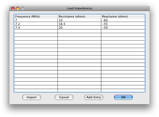
For this example, we will start with the following impedance data for the antenna:
Frequency   Resistance    Reactance
7.0 MHz     10.0          -60.0
7.2 MHz     16.5          -55.0
7.4 MHz     20.0          -50.0
We want to match all the points with an SWR of 2.0 or better.
First, let's start with a new window (ignore the impedance/SWR values from the cursor position):
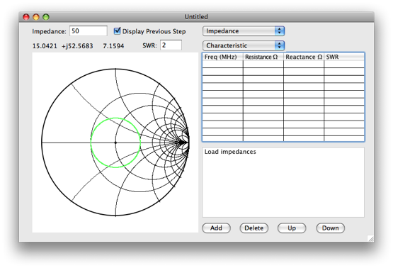
Next, we need to enter in our impedance Data.
Double click on Load Impedances:
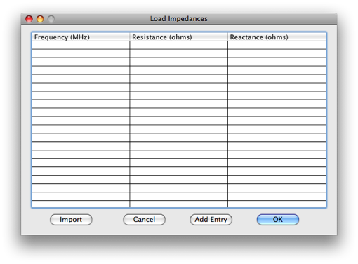
We're presented with an empty list of frequency and impedance pairs.
Click on Add Entry, and a new line will be added, with a frequency of 0:
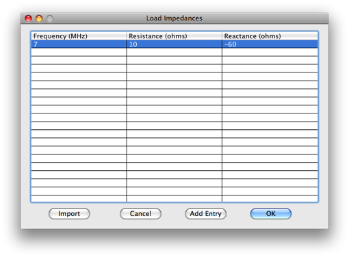
Double click on the 0 to edit it. Change it to 7 for 7 MHz. Do the same
for the resistance and reactance values to change them.
Repeat to add the impedances for 7.2 and 7.4 MHz:
Click OK.
Now we can see a plot of the impedance values.
The SWR for each point is also calculated:
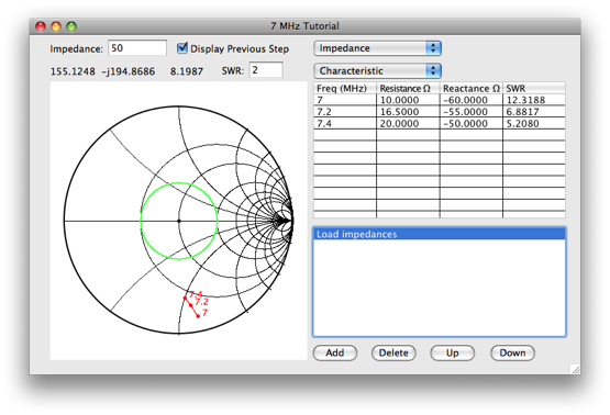
We want the impedance of the center frequency, 7.2 MHz, to be fairly close to 50 ohms,
for a good match. A shunt inductor will move the point to 50 ohms
(while a shunt capacitor would move it the opposite way).
Click Add, select a Shunt Inductor from the popup menu:
We'll try an initial value of 2 uH, so enter in 2, click Apply.
Click the new entry for Shunt Inductor 2 uH on the main window, to see the updated impedance in red:
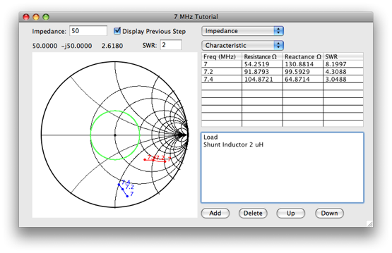
The impedance is too high, closer to 100 ohms, so we need more inductance.
Trying 3 uH, we get 44 ohms, closer, so now try 2.8, we get about 49 ohms, close enough:
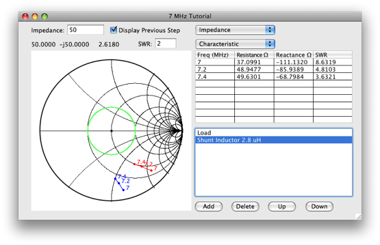
next we need to move the cluster of points into the green SWR=2 circle in the center of the graph,
using a series inductor.
Click Add, and select Series Inductor
We'll try 1 uH first, and find ou that it is not enough.
trying 2 uH, we find that it is much closer, and 2.1 uH centers the impedances nicely:
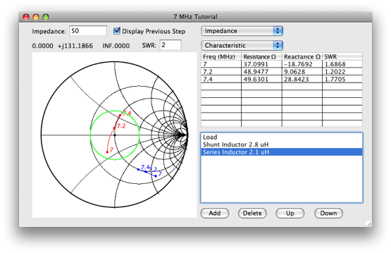
Note that when we started, our SWR values ranged between about 5 and 12, now they are all under 2!
Email your comments and questions to info@blackcatsystems.com
Last modified January 28, 2010
