Home
Lost Reg Code?
News
Online KiwiSDRs
macOS Software
Windows Software
Ham Radio iPhone/iPad
Linux Software
Support/FAQ
Update Policy
USB Icom CI-V Interface
Radio Hobbyist Products
22m Programmable Beacon Kit
CW Keyer For Beacons Kit
Jellyfish Transformer
Cyclops Antenna Transformer
General Interest Programs
Atomic Mac/PC
Audiocorder
Audio Toolbox
Black Cat Timer
Diet Sleuth
iUnit
Graffikon
Graph Paper Maker
Health Tracker
Image Resizer
Knitting Wizard
Label Wizard
Prog Audio Gen
Sound Byte
Synth 76477
Amateur Radio Programs
AirSpyHF+ Server
Audiocorder
Black Cat Absolute ACARS
Black Cat ACARS
Black Cat ALE
Black Cat ALE Vacuum Cleaner
Black Cat NetFinder
Black Cat GMDSS
Black Cat HF Fax
Black Cat SSTV
Black Cat NAVTEX SITOR-B
Carrier Sleuth
Cocoa 1090
Cocoa RTL Server
DGPS Decoding
DX Toolbox
Elmer
MatchMaker
KiwiKonnect
KiwiSDR Monitor
KiwiSDR Sound Client
MININEC Pro
Morse Mania
MultiMode
sdrRewind
RF Toolbox
SDRuno Plugin
SDRuno Equalizer Plugin
SelCall
Sonde
iPhone/iPad Apps
ALE
Atoms To Go
dB Calc
Clik Trak
DGPS Decoder
Drill Calc
DX Toolbox
Elmer Extra
Elmer General
Elmer Tech
Feld Hellschreiber
Field Strength Calc
Function Generator Pad
GMDSS
Godafoss
HF Weather Fax
iAttenuate
iFunctionGenerator
iSoundex
iSoundByte
iSweep
iUnit
Morse Mania
ACARS Pad
Morse Pad
NAVTEX Pad
Packet Pad
PSK31 Pad
SSTV Pad
Photon Calc
Rad Map Tracker
RF Link Calc
SelCall Tone Gen
Sound Byte
Sound Byte Control
Spectrum Pad
SWBC Schedules
Synth 76477
Synth Motion
Transmission Line Calc
Weather Calc
Wire Calc
iPhone/iPad Bundles
RF Calculator Apps
Ham Radio Decoder Apps
Audio Utility Apps
Shortwave Weather Apps
Ham Radio Exam Study Apps
Shortwave Decoder Apps
About Black Cat Systems
Site Map
Our software for Mac OSX
Privacy Policy
Press/Media
HFunderground
Apple /// Emulator
Macintosh Links
Shortwave Radio
Pirate Radio
Spy Numbers Stations
Science and Electronics
Ham Radio Software
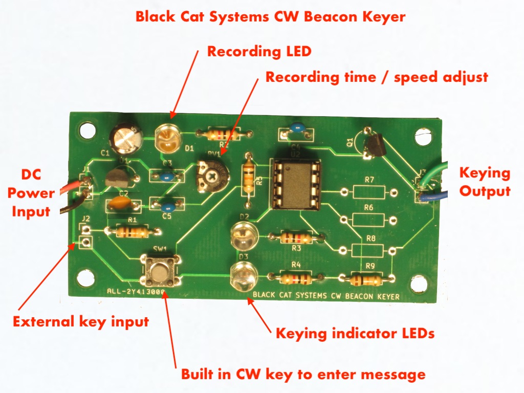
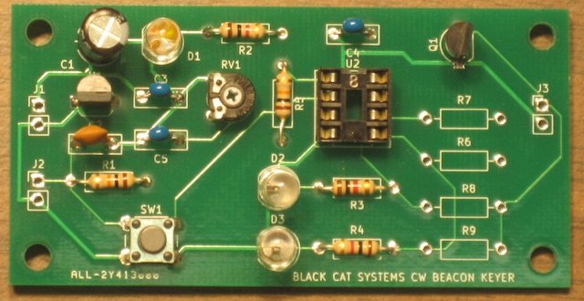
User Programmable Ham / Amateur Radio CW Keyer Kit For BeaconsJust $30 with Free Shipping! (We ship to the USA Only, we do NOT ship to Canada or elsewhere)This keyer kit is ideal for controlling your ham radio beacon. It features a non volatile EEPROM which stores your message, adjustable in length from about 6 seconds to one minute via a trimmer pot. There is a built in pushbutton for entering your message, and of course you can connect your own key to use instead, which is ideal for longer messages. The key samples the key input and stores 4096 readings, the trimmer pot sets the sample rate and therefore total message length. So it will preserve your "fist". You could of course also send a sequence of random length symbols in addition to morse code, or vary the CW WPM. The board has an output that you configure, one of four possibilities. Either a 0/5 volt output to control the transmitter key input, either normal or inverted polarity. Or an open collector output which can sink current from the transmitter key input, again normal or inverted polarity. Programming the board is simple, and can be done repeatedly (the EEPROM is rated for 10,000 write cycles), so you can change the message whenever you wish. Pressing down on the key to begin your message starts the recording process. An LED turns on while it is recording. You can continue to enter your message, up to the maximum time set by the trimmer pot. When the recording period is done, the LED will turn off, and the unit will sleep for a few seconds, so it won't start recording again if you accidentally tap the key. While recording, the red LEDs will turn on and off with the keydowns. After recording is finished, the keyer will begin transmitting the message, and immediately repeat after the end, with no additional delay, so build the inter-message delay you want to use into the end of your message. Click any image on this page to view it full sized
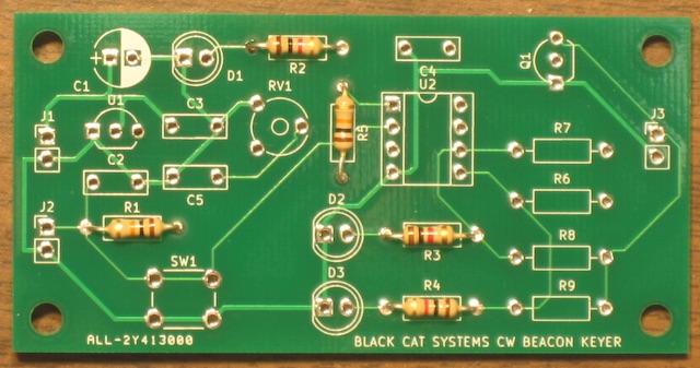
The kit includes the PCB and components, including a programmed microcontroller. Small size - just 3 by 1 1/2 inches. Easy to build, just a few components, all through hole, no surface mount. Full instructions on this page, just keep reading!
You can contact me via email prior to ordering with any questions.
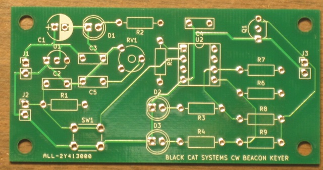
Circuit detailsBelow is the schematic. Click on it to view full sized:Parts List: Ref Value C1 100 uF C2 470 pf C3 0.047 uF (or 0.1 uF) C4 0.047 uF (or 0.1 uF) C5 0.047 uF (or 0.1 uF) D1 LED D2 LED D3 LED Q1 2N4401 NPN transistor R1 10K resistor R2 1K resistor R3 1K resistor R4 1K resistor R5 10K resistor R6 Application specific - install only one R7 Application specific - install only one R8 Application specific - install only one R9 Application specific - install only one RV1 100K trimmer potentiometer SW1 Pushbutton switch U1 MCP1702-5002E/TO92 - 5 volt regulator U2 ATTINY85-20PU - Programmed PCB 8 pin IC socket 10K resistor for R6/R7 U1 is a 5 volt low drop out voltage regulator. It, along with C1 and C3 provide the 5 volt power supply used by the microcontroller U2. Power to the board is applied at J1, maximum 12 volts. If it is desired to power the board from 5 volts, U1 can be left out and pins 2 and 3 of the U1 footprint shorted with a piece of jumper wire, although from testing it has been noted that the dropout voltage is nearly zero, and the board can be driven from 5 volts even with U1 installed. Current consumption is quite low, typically 5 mA, nearly all for lighting one of the two LEDs (10 mA when programming because the LED is also on). Higher current draw would occur of course if a load is connected to the J3 output that draws current. If even lower current consumption is required, R2/R3/R4 could be changed to larger values for less LED current draw (and a dimmer LED output) or even removed after programming the message. U2 is an ATTiny85 microcontroller, programmed with software to run the keyer. It has a built in oscillator. Pin 4 is ground and pin 8 is the 5 volt power input. Pin 1 is the reset line, held high by R5. Digital input PB3 (pin 2) is is CW key input, and is monitored by software. It is pulled up to 5 volts by R1, and C2 provides some filtering. There is a built in pushbutton SW1 that can be used for keying, and an external key can be connected across J2. Only a key/switch should be connected to J2, never a power source, or the board will be damaged. PB4 (pin 3) is an analog input, fed by potentiometer RV1. It is also monitored by the software, and used to set the sample rate for the CW message. Digital output PB2 (pin 7) drives LED S1 to indicate when the board is in programming mode. Digital output PB1 (pin 6) is driven high when the microcontroller is keying the CW output line. Digital output PB0 (pin 5) is a complementary (inverse) signal. This allows for both normal and inverse keying, depending on the transmitter needs. The keyer output is on J3. There are four possible output configurations:
Note: Be sure to only install one of the four options, or the board will be damaged. Also be sure to carefully check the keying requirements of your transmitter, to avoid damage. Black Cat Systems assumes no responsibility for damage caused by improper wiring, connections, or any use of the keyer board.
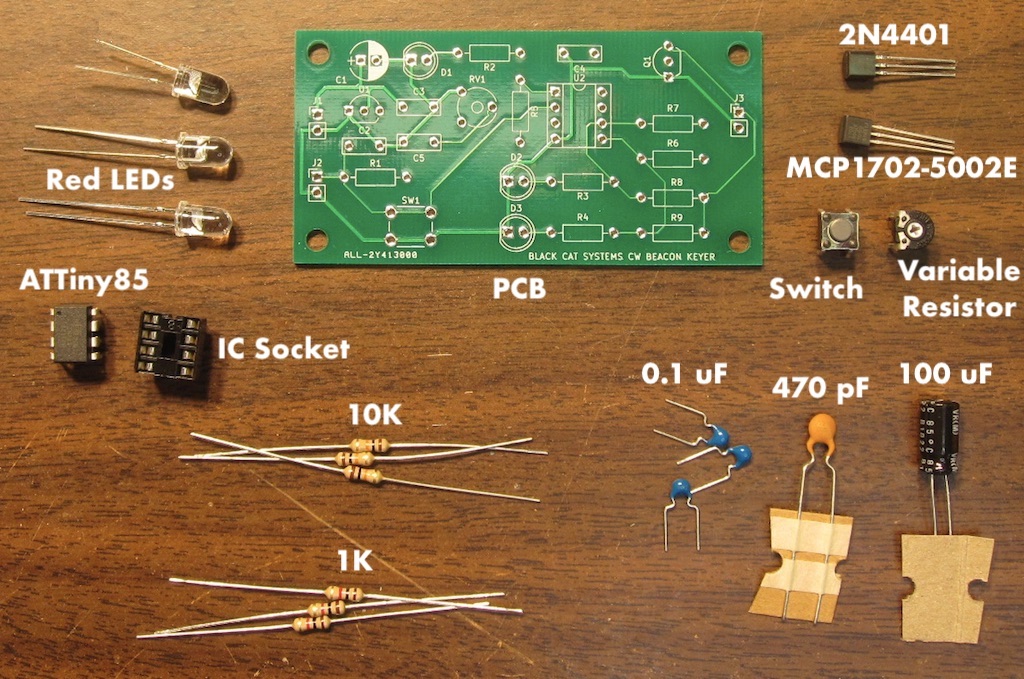
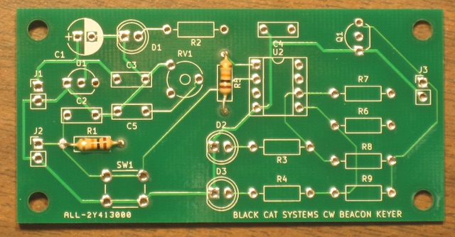
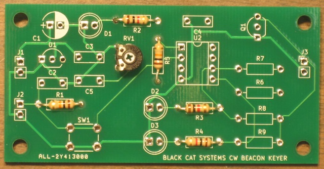
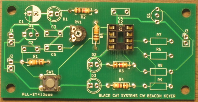
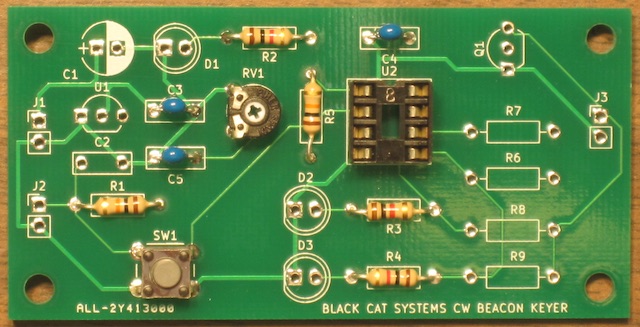
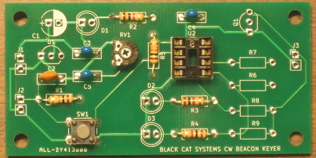
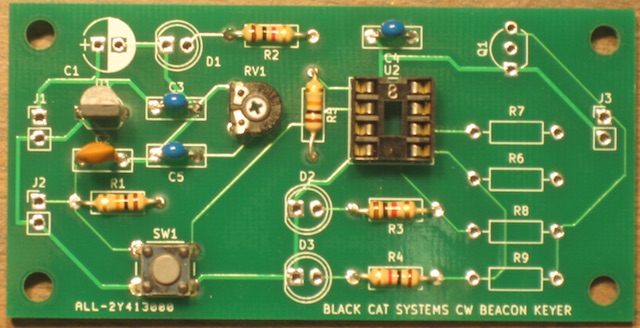
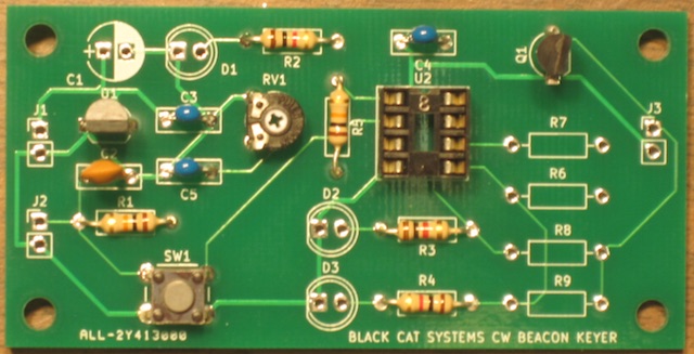
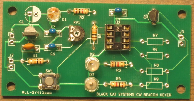
Assembly InstructionsNote: While it is believed that the assembly details and schematic are correct, there is always the possibility for a typo. If you believe this is the case, or have any questions, please contact me prior to assembly, to verify the correct steps. I want to you succeed!Below is a photo of all the components. Click to view it, as well as the other photos, to full sized. Familiarize yourself with each part, to avoid assembly errors.
Remove power, and carefully install U2 in the socket. Note the orientation, and make sure all pins are correctly installed (not bent). Make sure the IC is not backwards or it will get very hot and fail (ask me how I know). Rotate RV1 fully counter clockwise (CCW) for a minimum recording time, about 8 seconds. If everything is working well, one LED, typically D2, will be on. This is because the default EEPROM memory values are all 1s, so the output is keyed on the entire time. Press the pushbutton, and the recording LED will turn on, D2 will also be on. Release the button, the LED will remain on, D2 will turn off and D3 will turn on. You can press the button a few more times, each time it is pushed, D2 will be on and D3 will be off, vice versa when it is not pressed. After about 8 seconds, the LED will turn off, indicating recording has finished. Then the unit will pause for about 5 seconds, and then it will begin playing the recorded CW message, which is probably just the random pushbutton sequences you entered. Next you can experiment with keying some actual morse code. You can of course connect a real key at J2, which will make it easier to send good CW vs the pushbutton. You can also increase the recording time by rotating RV1 clockwise. When you rotate it in playback mode, it will also adjust the playback rate, making it slower or faster than when it was recorded. Below is a video showing the board in action, from power up:
|
Email your comments and questions to info@blackcatsystems.com
Last updated April 19, 2024

