Home
Lost Reg Code?
News
Online KiwiSDRs
macOS Software
Windows Software
Ham Radio iPhone/iPad
Linux Software
Support/FAQ
Update Policy
USB Icom CI-V Interface
Radio Hobbyist Products
22m Programmable Beacon Kit
CW Keyer For Beacons Kit
Jellyfish Transformer
Cyclops Antenna Transformer
General Interest Programs
Atomic Mac/PC
Audiocorder
Audio Toolbox
Black Cat Timer
Diet Sleuth
iUnit
Graffikon
Graph Paper Maker
Health Tracker
Image Resizer
Knitting Wizard
Label Wizard
Prog Audio Gen
Sound Byte
Synth 76477
Amateur Radio Programs
AirSpyHF+ Server
Audiocorder
Black Cat Absolute ACARS
Black Cat ACARS
Black Cat ALE
Black Cat ALE Vacuum Cleaner
Black Cat NetFinder
Black Cat GMDSS
Black Cat HF Fax
Black Cat SSTV
Black Cat NAVTEX SITOR-B
Carrier Sleuth
Cocoa 1090
Cocoa RTL Server
DGPS Decoding
DX Toolbox
Elmer
MatchMaker
KiwiKonnect
KiwiSDR Monitor
KiwiSDR Sound Client
MININEC Pro
Morse Mania
MultiMode
sdrRewind
RF Toolbox
SDRuno Plugin
SDRuno Equalizer Plugin
SelCall
Sonde
iPhone/iPad Apps
ALE
Atoms To Go
dB Calc
Clik Trak
DGPS Decoder
Drill Calc
DX Toolbox
Elmer Extra
Elmer General
Elmer Tech
Feld Hellschreiber
Field Strength Calc
Function Generator Pad
GMDSS
Godafoss
HF Weather Fax
iAttenuate
iFunctionGenerator
iSoundex
iSoundByte
iSweep
iUnit
Morse Mania
ACARS Pad
Morse Pad
NAVTEX Pad
Packet Pad
PSK31 Pad
SSTV Pad
Photon Calc
Rad Map Tracker
RF Link Calc
SelCall Tone Gen
Sound Byte
Sound Byte Control
Spectrum Pad
SWBC Schedules
Synth 76477
Synth Motion
Transmission Line Calc
Weather Calc
Wire Calc
iPhone/iPad Bundles
RF Calculator Apps
Ham Radio Decoder Apps
Audio Utility Apps
Shortwave Weather Apps
Ham Radio Exam Study Apps
Shortwave Decoder Apps
About Black Cat Systems
Site Map
Our software for Mac OSX
Privacy Policy
Press/Media
HFunderground
Apple /// Emulator
Macintosh Links
Shortwave Radio
Pirate Radio
Spy Numbers Stations
Science and Electronics
Ham Radio Software
The Jellyfish - Universal Matching Transformer for Beverage / Longwire / Dipole / Random wire / K9AY / LoG Loop on Ground / Flag / EWE AntennasJust $69 with Free Shipping! (USA Only)Transformers are made in small batches, and sometimes are not available for immediate shipment. If you'd like to place an order, please contact me at info@blackcatsystems.com and I can let you know what is currently available and how to place an order. Thanks!
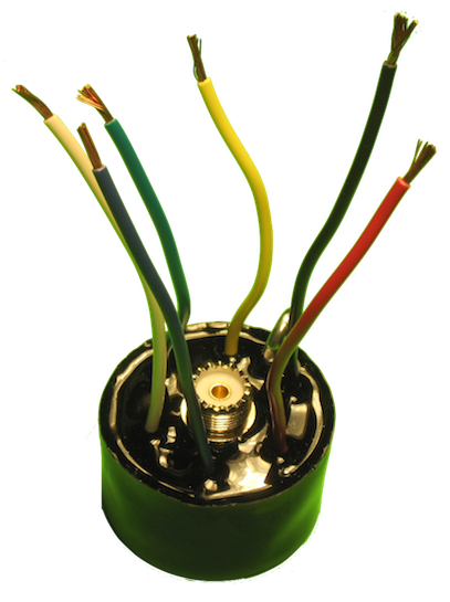
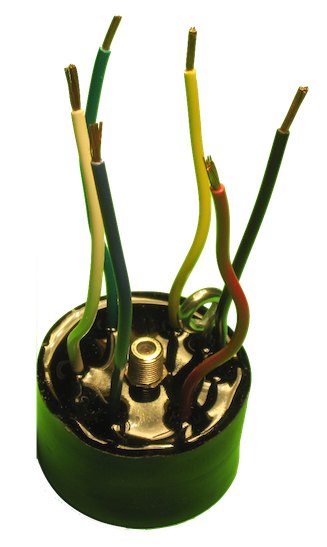
Now available, an epoxy resin potted version of our famous Squid matching transformer. Excellent protection against moisture. The big advantage over a regular matching transformer that only handles one impedance is this one has a tapped transformer. So it can match a wide range of antennas. And you don't even need to know your antenna's impedance, try the combinations and pick the best one. And if your antenna changes, you don't need a new transformer, just change the pair of wires you use. Easy! Proper matching of your antenna is critical if you want the best possible performance. While small impedance differences do not cause significant problems for receiving antennas (unlike transmitting applications where the resulting high SWR is a problem), large differences can. Your radio's antenna connector typically has a 50 ohm impedance, however the impedance of your antenna can be significantly different. This is especially true for Beverage, Random wire (Longwire), K9AY, Flag, Pennant, Ewe, and Folded dipole antennas which tend to have much higher impedances. Directly connecting these antennas to the 50 ohm coax running to your receiver results in a significant impedance mismatch, with high losses resulting in weaker signals. The antenna's pattern can also be affected. The net result - your antenna is not working as well as it should (and it could in fact be working very poorly). This is solved by using a matching transformer, which allows maximum signal transfer between your antenna and receiver. This is not a problem - if you know the actual impedance of your antenna. However, most of the time you don't. Even if you used a published antenna designed, or modeled your antenna with software, the actual impedance of the antenna is often different, perhaps significantly different, than the design impedance. The solution is our matching transformer which allows a range of impedances to be matched to 50 ohms. The primary (antenna side) of the transformer is tapped, so it can match numerous impedances to a 50 ohm output. There are six wires on the primary side. Based on which combination of two of these wires are used, a range of impedances can be matched to 50 ohms. Each wire is a different color, so it is easy to determine which wires to use. And even if you don't know the actual impedance of your antenna, it is still easy to use. Just try the various combinations, and determine which works best with your antenna. And should you change your antenna, resulting in a different impedance, you can still use the transformer, just select a different combination of wires, resulting in a different impedance. No need to buy or build a new transformer. Connection of the transformer is easy. Select two of the six wires, based on the known impedance of the antenna, or through experimentation. The antenna wire and ground wire are connected to these two wires. To provide strain relief, they should be coming off an antenna insulator or other support. Do not connect the antenna or ground wires directly to the transformer wires without doing this, or the wires could be pulled out, damaging the transformer. The connections should be secured with wire nuts and/or electrical tape (which you supply). The four unused wires should also be covered to prevent corrosion, should you wish to use them in the future. Their short length will not cause appreciable unwanted RF pickup. The eyebolt at the top of the transformer can be used to hang it for mounting. Again, make sure there is no strain on the transformer. The following table shows the nominal matched antenna impedance for each combination of two wires. Due to the number of turns in each tap, a few values get repeated. As the transformer primary and secondary are insulated, the wire you use for the antenna and ground connections does not matter for most antennas. Exact impedance matching is not required for most antennas, the values covered by the transformer allow a wide range of antennas to be matched. Impedance Chart:
The two versions have a different number of turns on the primary of the transformer. These are the nominal output impedances vs 50 ohms with the UHF connector version and 75 ohms with the F connector version. If you were to use a 50 ohm coax connection with the F connector version then the effective output impedances would be about 2/3 of the values above. If you were to use a 75 ohm coax connection with the UHF connector version then the effective output impedances would be about 3/2 or 50% higher than the values above. Note: This transformer is for receive only applications, not for transmitting. Transmitting into it will damage it and possibly your radio. It does not provide protection from lightning. You should always use a lightning arrestor with any antenna, and follow the appropriate electrical wiring codes. Antennas should be disconnected during storms for maximum safety, and to prevent damage to the transformer, and your radio. All antennas must always be kept away from power lines, with no possibility of contact under any circumstances.
Just $69 Free Shipping (We ship to the USA Only as international shipping is too expensive)
|
Email your comments and questions to info@blackcatsystems.com
Last updated March 29, 2025


